


To better understand what cathodic protection is; We must know that this method is one of the most effective methods of corrosion control. In this way, industrial structures, pipes and equipment installed underground or underwater are protected.
Only corrosion attacks that are accompanied by electrochemical reactions and changes in material valence can be controlled by cathodic protection.
What is the basis of cathodic protection
Cathodic protection systems are based on the application of cathodic current and the reduction of potential and corrosion current of parts that are subject to corrosion attacks.
What are the two main methods for cathodic protection:
- Sacrificial anode method
- Impressed cathodic current protection (ICCP)
In order to better understand the concepts of potential and corrosion current, we need to know Mixed Potential Theory.
The mixed potential theory was introduced by Wagner. This theory was proposed in 1938 and is based on two important hypotheses:
1. Each electrochemical reaction is a set of at least two or more oxidation and reduction reactions.
2. The sum of the charges exchanged in an electrochemical reaction is zero. In other words, the sum of the oxidizing current is equal to the sum of the decreasing current (the principle of charge survival).
![]()
Based on this theory, flow-density diagrams (i E-log or Evans) have been drawn, which are known as the basic principles of cathodic protection.
Although this theory is very practical, it is not error free. The coupon method is considered as the safest method to determine the corrosion rate.
Now, in the article “What is cathodic protection”, the subject of “corrosion coupons” is mentioned, we will provide a brief explanation about it. You can read the full article “Corrosion Coupons“ on Naftan Payesh website.
Corrosion coupons:
Corrosion coupons are a very simple and effective tool that provides a small estimate of the rate of corrosion that occurs within a particular operating system. Coupons also provide an objective signal of the type of corrosion that may occur in the monitored system.
This method involves placing a sample of material (coupon) in a process environment for a certain period of time, then sampling it for analysis. The basic measure of corrosion coupons is weight loss. Weight loss during the period of exposure to the environment is expressed as the rate of corrosion.
Corrosion coupons are also known as corrosion monitoring coupons.
What is the meaning of Mixed Theory in cathodic protection
Here we examine what the concept of mixed potential in cathodic protection is. The figure below shows an image of a piece of zinc (Zn) immersed in hydrochloric acid (HCl).
According to Wagner’s theory, for the reaction of dissolution of zinc in hydrochloric acid, two halves of anodic and cathodic reactions can be considered:
Half anodic reaction of zinc oxidation
![]()
Half cathodic hydrogen reduction reaction
![]()
These two half-reactions are occurring simultaneously on the metal surface. Each half reaction has its own potential and current density.
It is important to note that these half-reactions cannot be present separately and at the same time on the zinc surface (Zn). So they have to adapt their potential to what is called the corr E potential.
In fact, what we know as corrE is the combination of the potentials of the two halves of anodic and cathodic reactions, and this is the concept of mixed potential.
Cathodic protection: What is corrosion
What are Evans or Evans Diagrams in Cathodic Protection
The vertical axis of these diagrams shows the potential for a standard electrode reference and the horizontal axis the logarithm of the current density.
Drawing Evans diagrams requires equilibrium potential (0E) and exchange current (0i) and straight anode and cathode lines.
It should be noted that an electrochemical corrosion system can be characterized by kinetic parameters. Such as TOEFL slope (cβa, β), exchange current density (0i) and limit current density (li).
But E0 is a thermodynamic parameter and is obtained for each reaction from the EMF series in the equilibrium state of the substance with its ion solution.

What is cathodic protection; The equation does not exist
The electrode potential (Ecorr) and the current density (icorr) are obtained from the point where the lines of hydrogen reduction (H + / H2) and oxidation of zinc (Zn+2 / Zn) intersect.
Exchange current density (0i) and open circuit potential (OCPE) are required to plot graphs.
This type of flow potential-density diagram can be drawn for all solids that have one or more oxidizing agents in contact with the solution. The calculations needed to draw the lines can be done using electrochemical equations.
Like the Nernst equation and the reactions written on the anode and cathode lines:
![]()
What is corrosion flow and corrosion potential in cathodic protection:
Corrosion current and corrosion potential are obtained from the intersection of the anodic and cathode lines of these diagrams. If we have several oxidizing or reducing factors, due to the principle of equality of oxidation and reduction currents, the flow and corrosion potential can be calculated.
If an oxidizing component such as ferric ion is added to the solution, the corrosion potential can be calculated on the Evans diagram. This is done with the help of the principle of equality of oxidation and reduction current.

Conclusions from Wagner's theory
In the following; Our conclusion from Wagner’s theory in the article “What is cathodic protection“:
What can be deduced from Wagner’s theory of mixed potential is summarized as follows:
- Corrosion flow increases with the addition of secondary oxidizing species.
- The corrosion potential tends to be more positive with the addition of a secondary oxidizing species.
- The rate of hydrogen release decreases with the addition of oxidizing species.
Today, with the advancement of technology, we are able to obtain graphs without calculations that increase the speed of calculating the flow and the corrosion potential. This is done using a potentiostat device and a three-electrode tube that includes a reference electrode, a platinum electrode, and a sample.
The graphs obtained from corrosion testing devices are slightly different from the theoretical image we have of Evans diagrams. These charts were first introduced by Julius TOEFL and are known as TOEFL charts.
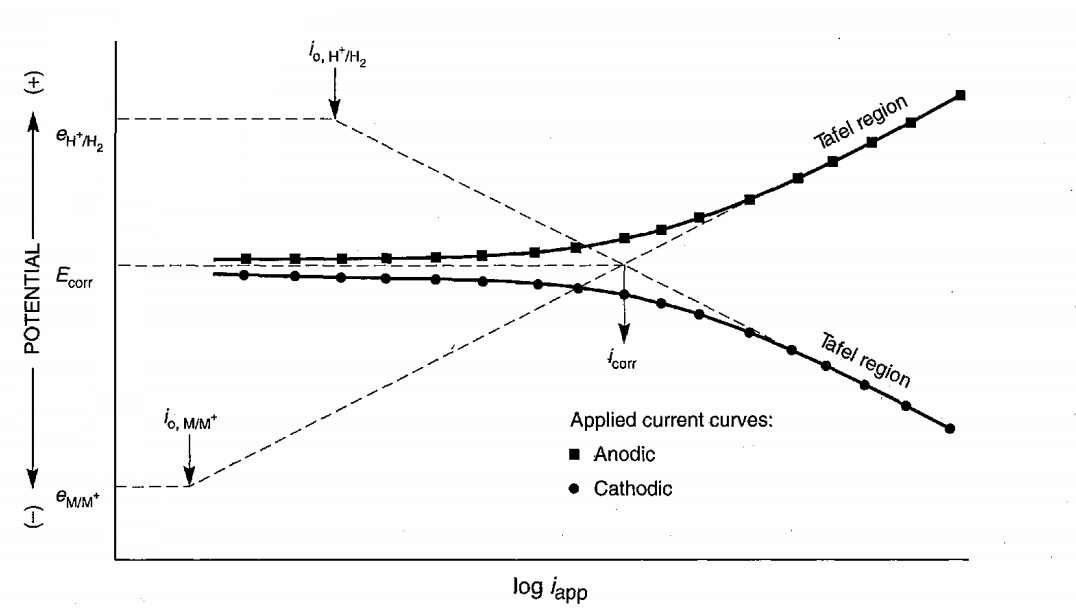
What are Tafel Diagrams in Cathodic Protection
What are TOEFL diagrams in cathodic protection? The following figure shows an example of TOEFL diagrams that are very crucial in calculating the cathodic protection current. The current and corrosion potential are calculated from the convergence of the tangent lines in the anodic and cathodic region.
The basis for drawing these diagrams is the application or discharge of electrons on the surface of the sample in order to increase or decrease the potential by means of a potentiostat device. The current is then read according to the applied potential. Potential is in the role of stimulus and its response flow.
When corroded, the sample or metal is in equilibrium with the environment, and the potential read is known as the open potential (OCPE). But by sending electrons to the surface, we are able to apply a more negative potential than corrE to the sample surface.
If we want to create more positive potentials, we have to take the potential out of the electron surface.
Description of TOEFL metal diagrams
What is the most important consideration in cathodic protection?
What is considered in cathodic protection is to keep the equipment at a potential more negative than the corrosion potential. For example, if the iron potential in the medium it is in contact with is -0.6V vs.SHE, to protect it, the potential can be increased to -0.8V vs.SHE. SHEHOLDED.
Since the principle of equality of the sum of anodic and cathodic currents is established according to Wagner theory and the cathodic current is greater than the anodic current, we can understand the role of cathodic action current that compensates for the difference between cathodic and anodic currents on the graph:


The figure above shows that to compensate for the difference between the anode and cathode currents, the device must apply electrons to the sample or equipment.
As a result, what is applied in cathodic protection as a cathodic flow is obtained based on TOEFL diagrams. Which compensates for the cathodic current required to keep the equipment at the desired cathodic potential and to protect the equipment or structure.
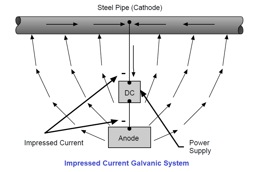
For cathodic protection, a circuit is designed as shown in the image below.
In this circuit, we use an external anode through which current can be applied to the surface of the metal or structure. The metal will cathode as an electron receptor. In order to maintain current, we always need an electrical connection and an ion conduction path.
What is cathodic protection; Cathodic protection by sacrificial anode (galvanic anode)
In this section, what is the role of the sacrificial anode in cathodic protection?
Sacrificial anode systems operate on the basis of potential differences resulting from corrosion of metals or alloys.
This method uses a more active metal such as zinc, magnesium or aluminum to protect iron or steel structures. This metal is in the EMF series lower than iron.
For example, the natural corrosion potential of iron relative to the reference of copper / copper sulfate electrode is between -0.4 to -0.6 volts. While the corrosion potential of zinc relative to the reference of copper / copper sulfate electrode is -1.1V.
Therefore, if the two metals are electrically connected, the potential difference between iron and zinc will be approximately 0.5 to 0.7 volts. Zinc (Zn) corrosion will also occur and iron corrosion will be prevented.
It is important to note that cathodic protection is provided that both metals are in the same electrolyte. As well as electrical and ionic conductivity between the anode and the cathode. The metal that is eaten is the anode and the metal that is protected is the cathode.
Everything that has been said about galvanic corrosion also applies to self-sacrificing anode protection.
In this method, the sacrificial anode is placed near the structure and in the soil and the electrical connection is established by metal cables. Due to the potential difference between the anode (more active metal) and the structure, current is established on the surface of the structure and its corrosion intensity decreases.
It should be noted that the ionic and electrical conduction path must be established, otherwise the current will not be established. Also, both more active and noble metal will be eaten.

What is cathodic protection; Wagner Theory and Mixed Potential
In this section of “What is Cathodic Protection”, the question is: When will the more active metal be eaten more?
By Wagner’s theory (![]() ) And the mixed potential, it can be proved that the more active metal (zinc or magnesium) will be corroded more than when it is only in the soil. Also,the more noble metal (Fe) will be less corroded and so-called protected.
) And the mixed potential, it can be proved that the more active metal (zinc or magnesium) will be corroded more than when it is only in the soil. Also,the more noble metal (Fe) will be less corroded and so-called protected.
The following figure shows that in the presence of Zn, the intensity of the corrosion current density of iron (corr, Fe ’i) Compared to when iron alone is in corrosive solution (corr, Fe i) Will be less and vice versa the intensity of the corrosion current intensity on (corr, Zn ’i) Compared to when it is in corrosive solution alone (corr, Zn i) Will be more.

Components of a sacrificial anode system
1- Sacrifice anode
Based on the galvanic activity, other characteristics and price, the appropriate anode is determined. Active metals such as zinc, magnesium and aluminum are used as sacrificial anodes. These metals, when bonded with iron, provide the current needed for protection.
?What are the three most widely used anodes in cathodic protection
The table below compares the properties of three widely used anodes in cathodic protection such as density and potential relative to the copper / copper sulfate reference electrode.

It is observed that aluminum and zinc have potentials close to each other and magnesium has the most negative potential.
Anode power indicated by ampere-clock is another important factor to consider in the design. Although the magnesium anode has the most negative potential, it has less power than other anodes and more weight must be used to achieve a certain current.
Zinc anode and its features
The anode density is 4 times that of magnesium and a heavy anode, and it provides less current than magnesium and aluminum. Zinc anodes are more efficient in places where resistance is lower. These anodes work well in soils with a resistance of less than 1000ohm.cm, seawater, mixed seawater and freshwater.
Zinc anodes used for soil must be of high purity and are sometimes made of casting. They are sometimes combined with aluminum and cadmium. Up to 90% of zinc anodes can be converted to current. The remaining 10% is the anode drop due to the products that are formed on them.
The presence of small amounts of iron in the zinc anode causes a dense coating to form and prevent flow. The presence of iron is harmful even in small amounts, and the addition of aluminum and cadmium eliminates this defect.
Zinc used for soil anodes should be 99.99% pure. It does not suffer from severe polarization when placed behind a suitable strap.
Zinc anode current efficiency
Zinc anode current efficiency is almost constant and can vary from low to high depending on the chemical composition of the zinc anodes.
The potential of the zinc open circuit relative to the reference copper / copper sulfate electrode is -1.1V. If the steel structure is to be protected at a potential of -0.85 V, the potential difference will be -25.V. In the event of a large potential drop, this potential difference will be eliminated and protection will be inadequate.
Zinc anodes are available in weights ranging from 5 (2.3 kg) to 250 (113.4 kg). They also have different shapes, such as: Plate, bar and bar.
Sometimes ready-made straps are also used for zinc:
Such as Gypsum (a combination of calcium sulfate) and Bentonite (aluminum polysilicate). These conductive supports are suitable for zinc ions.
?Under what conditions can the zinc anode not be used
Zinc is not suitable for protection at pHs above 8 or temperatures above 50 ° C. Because in both cases, the surface is patio and is placed in a cathodic position relative to the structure and protection is not provided.
Magnesium anode and its properties
What is cathodic protection; In this section, you will learn about magnesium anode and its properties.
Magnesium is the most widely used sacrificial anode due to its reasonable price and performance. It is the best choice in soils with high resistance and seawater and a mixture of seawater and fresh water.
Magnesium anodes are available in weights ranging from 1 (0.45 kg) to 200 (90.7 kg) pounds. They also have different shapes, such as: Plate, bar and bar.
The magnesium anode is sometimes alloyed with aluminum (6wt%) and zinc (3wt%) to distribute the current evenly. Magnesium is more active than zinc and creates more potential difference. Therefore, it is expected to cause up to 4 times more local corrosion than zinc.
Magnesium is able to negate the potential of metal structures up to -0.9 volts. Now what do you think are the uses of cathodic protection? Magnesium anodes are used for cathodic protection of water tanks, heat exchangers and condensers.
The life of magnesium anodes is affected by the resistance of the environment and the backing. Magnesium anodes work better for high-strength soils. The cause can be traced to a more negative potential than zinc.
The higher the soil strength due to the high potential difference, the potential drop will be compensated and the structure will be protected at the desired potential.
Aluminum anodes and their characteristics
What is cathodic protection; In this section, you will get acquainted with the aluminum anode and its features.
The characteristic of aluminum index is the high current density that it creates on the surface, but because it has low potential, it is not suitable for high-strength soils. However, it can be a good option for use in seawater.
The main problem of aluminum is creating a protective layer Al2O3 ismercury or iridium used to solve this problem. However, mercury is not used due to environmental issues.
Aluminum is usually alloyed with zinc to increase flow efficiency.
1- Backfill, backfill or backfill
The sacrificial anodes are almost always placed in a bed called a backing to reduce soil resistance. As a result of this action, the anode efficiency will increase and more current will be taken from it. The backband increases the life of the anode and allows the current to be evenly distributed. At the same time, it prevents the accumulation of gas.
Coke base materials can be used for the back of the anode. Accumulation of corrosion and gas products destroys the anode. Finally, the backrest can reduce the potential drop.
2. Connection cable
What is a connection cable in cathodic protection?
The cable provides a strong connection between the anode and the cathode. A strong connection between the anode and the cathode is essential for cathodic protection.
The sacrificial anodes are either screwed into the structure or welded. Another method of connection is withlead wire insulation cable, which is either welded to the structure or connected by mechanical methods.
Another method of anode to connection structure is thermite welding. This welding is explosive or heat generating.
3- Test Station
Test station is a place that is installed to measure the potential of a pipe or structure in relation to soil, flow, output or anode efficiency, etc. The test station also allows us to monitor the cathodic protection system and take the necessary measures for proper protection.
4- Reference electrode
What are the limitations of the sacrificial anode method in cathodic protection?
- The amount of protection in terms of voltage depends on the potential difference between zinc and iron. Because the voltage difference is limited, the sacrificial anode must be located near the structure to be protected.
- IR drop is always present in the path of cathodicprotection. Which should be considered in the calculation and selection of the type of sacrificial anode and the maximum potential difference is 1 volt. For example, if there are rocks and other high-strength components in the path, a more active metal such as magnesium should be used.
- Due to the limitation of the potential difference (less than 1 volt), in case of potential drop and high resistance, the efficiency will be low.
- Galvanic systems are more efficient in small or covered structures.
- The applied current density on large structures with high levels will be negligible.
- If the electrolyte is water, its resistance should not exceed 200ohm.cm. More resistance will reduce the current distribution. In case of more resistance, more anodes should be used.
- Another limitation is the pH, which should be between 5.5 and 11, and the temperature, which should not exceed 60 degrees Celsius.
Types of sacrificial anodes
What are the types of anodes sacrificed in cathodic protection?
The three metals zinc, magnesium, aluminum, and their alloys are commonly used to make sacrificial anodes in the form of blocks, rods, trapezoids, plates, disks, or strips.

What is cathodic protection; Cathodic protection by applying current
The sacrificial anode system is capable of providing limited potential differences. Unlike the sacrificial anode system, the current application system is capable of supplying a potential difference of 100 volts or more. Therefore, for large structures, it is preferable to use the flow method.
The power source can be a solar cell, a battery or a rectifier. The negative pole of the current generator is connected to the cathode and the positive pole is connected to the anode.

What potential can we apply to the cathodic protection of various structures?
This table shows that in the presence of sulfate-reducing bacteria (SRB) we must apply sufficient electrons to the surface of the steel structure. To the extent that we reach a potential of -0.95 volts based on copper electrode / copper sulfate.
We need to apply more potentials for the cathodic protection of aluminum.

What is cathodic protection; System anodes apply current
These materials are used because they have low weight loss due to high current generation and are suitable for potential difference of 100 volts and high current density.
Finally, a large area of the structure can be protected with this anode, and the anode can be located at a great distance from the structure. Depending on the anode used on the anode side, a water decomposition reaction or iron corrosion can occur. Therefore, it is better to use a material that is a conductor of flow and does not suffer from corrosion, such as graphite.
Design of cathodic protection systems
What is the design of systems in cathodic protection?
Different standards are proposed for the design of cathodic protection systems:
- NACE Standards
- DNV Standards
- British Standards (BS)
Among the mentioned standards, the standards designed by NACE are the most important.
The first step in designing acathodic protection system for a tank, pipe, and metal structure is to decide on the type of protection system. The type of protection system can be a sacrificial anode, current injection, or a combination of both.
When is the flow injection system used?
- When the structure is large.
- When the sacrificial anodes will not be able to supply the required current.
Economic factors can also play a very important role.
In order to further clarify the criteria, the advantages and disadvantages of both systems should be considered.
Advantages of the sacrificial anode system
- Easy to install
- Independence of flow supply systems
- Suitability to protect a specific area
- Less interference with adjacent structures
- Over-protection is unlikely to occur
- Uniformity of potential in different parts of the structure
What are the limitations of sacrificial systems in cathodic protection?
- Limited potential difference and injectable current
- Complicating the installation of a large number of anodes and the presence of electrical connections
What are the advantages of a flow injection system in cathodic protection?
- Apply a higher potential difference that allows the protection of a large structure without cover in a high-strength environment.
- Compared to a sacrificial anode system, fewer anodes are required.
- Voltage can vary depending on changes in environment and coverage.
What are the limitations of the flow injection system in cathodic protection?
- If there is not enough control, this system can over-protect the structure.
- Significant potential changes to the structure can be unavoidable.
It can be concluded that the dehydration system is suitable for small structures and current injection for large complex systems that do not have proper coverage or no coverage. Also use when the soil has a higher resistance.
What is a cathodic protection system?
In Antarctica, for example, it is quite cost-effective to use a sacrificial anode system for uncoated platforms where the cost of coverage is very high. Another effective factor is the lack of need for sacrificial anodes to supply electricity.
Principles of cathodic protection system
What are the principles of cathodic protection system?
The whole cathodic protection system is considered equivalent to one circuit. Regardless of the type of system to be implemented, three distinct criteria must be calculated:
1- What is the determination of the final current in cathodic protection?
The first parameter to be considered in the design of a cathodic protection system is the current. The whole structure is considered as a circuit. This current can be calculated by multiplying the required current density at the structural level or determining the actual current.
s I = i.A
The required currents for some alloys, such as steel, are listed in the sources.

2- What is the determination of the final resistance in cathodic protection?
The next step in designing a cathodic protection system is to determine the resistance. This resistance depends on many factors. In many systems, the strength of the anodic substrates is a controlling factor. This resistance is also a function of soil resistance.
It is usually considered a set of resistors. Like the following:
- Electrolyte resistance of the anode (a/e R)
- Relative to the electrolyte (s/e R)
- Cable resistance
tip: There are many equations for obtaining anode resistance to an electrolyte.
Rtotal = Rsoil + Ranodicbed + Rcable
3- What is the voltage and size of the rectifier in cathodic protection?
totalV = Rt.otalI
In practice, the required voltage and current may be greater than what is calculated. The structure may be covered at first and disappear after a while, or there may be a gap between the cables. For example, the voltage can be considered up to 1.5 times higher.
What is cathodic protection; Other points to consider when designing a cathodic protection system include the following.
What is the amount of anode used in cathodic protection?
If the anode system is sacrificial and the anode is consumed directly, the required anode weight is obtained from the anode corrosion rate at the current specified for it.
What is the number and distribution of anodes in cathodic protection?
- The weight of the anode used can be divided into several anodes. Also, the more uniform the anode distribution, the better the cathodic protection current distribution.
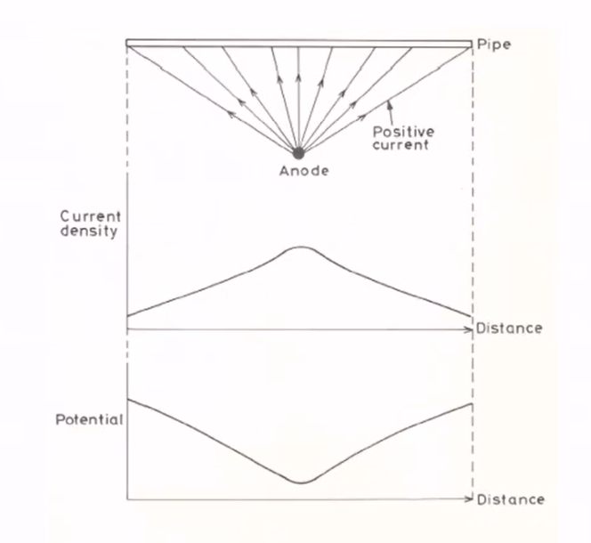
- The closer the anodes are to the structure, the higher the efficiency.
- The anode surface also oxidizes after a while and becomes corroded. Therefore, it will not have the initial efficiency, so the current drop should be considered.
The following figure shows that the closer the anode is, the more negative the voltage and the higher the current.
What is the resistance of the anodic bed in cathodic protection?
From the number and distribution of anodes, the resistance of anodes is obtained by experimental formulas. In these formulas, the resistance is determined according to the position and shape of the anodes.

Software simulations are also used today. This is due to the cost of drilling and other factors of cathodic protectionsystems.
In the article “What is cathodic protection” we tried to provide you with up-to-date content, so that you can get complete information about this issue.
be successful and victorious.
Source
M. G. Fontana, Corrosion engineering, Third edition, McGrow-hill book company, 1910.
D. A. Jones, Principle and prevention of corrosion, Prentice Hall, 1996.
https://link.springer.com/chapter/10.1007/978-3-319-24847-9_7.
Types of Cathodic Protection for Pipeline Protection


